
 The purpose of this article is to describe a new cleaning procedure for thoroughly cleaning WPI flowcells, including Liquid Waveguide Capillary Cells (LWCCs), UltraPath flowcells and optical cuvettes.
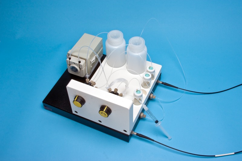
The image (right) shows a 3000 series LWCC with a MiniStar pump and the LWCC injection system placed on top of it.
Preparation of Chemicals
All chemical reagents should be of at least ACS-Grade, preferably HPLC-Grade. This procedure involves the use of caustic and flammable reagents. Consult the manufacturer’s MSDS for necessary safety precautions.
Cleaning Solution #1:
0.5M Potassium Hydroxide in 100% Ethanol (e.g.: 7 g KOH in 250mL EtOH). After thoroughly mixing, filter the solution through a 20µm pore size filter.
Cleaning Solution #2:
100% Methanol, HPLC grade
Cleaning Solution #3:
Ultrapure water, Type I per ASTM D1193-99 or equivalent
NOTE: Grade 1 ultrapure water per ISO 3696 differs significantly from the above classification.
Cleaning Procedure
 The preferred method of cleaning involves the use of a spectrometer (e.g. Tidas E Base) or photometer based detection system in “monitor mode” throughout the entire cleaning process. This allows the technician to observe the extent of performance improvement as a function of time.
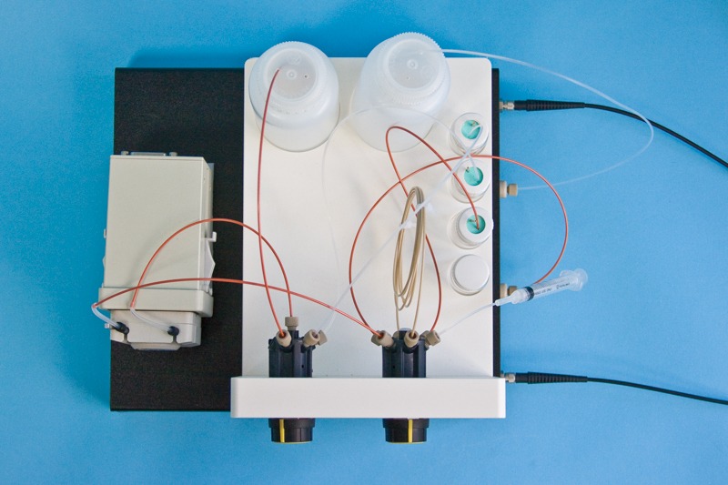
The image (right) shows the top view of a MiniStar pump and an LWCC Injection System. The injection system has the DIW and Waste containers at the back, and the three cleaning solutions and a sample bottle on the right side.
The simplest cleaning method involves using a peristaltic pump (#MiniStar) to flow each cleaning solution through the sample cell in the appropriate order. A convenient way to perform this task is to use WPI’s LWCC Injection System (#89372). It is recommended that the pump be configured to “pull” through the cell to avoid possible contamination from degraded peristaltic pump tubing. Each solution is cycled for approximately 3-4 minutes, with a bolus of air introduced between each solution. This procedure is repeated until there is no noticeable improvement in sample cell performance. The flow direction can be reversed between cycles to ensure a thorough cleaning.
To lessen the time required for the above cleaning method, large bubbles of air can be introduced into the sample cell alternately with the cleaning solutions. This method uses a laminar flow profile and radial diffusion to effectively “scrub” the inside of the sample cell.
It is imperative that Solution #2 immediately follow Solution #1 to remove residue remaining on the optical components. Failure to do so will result in poor flowcell performance.
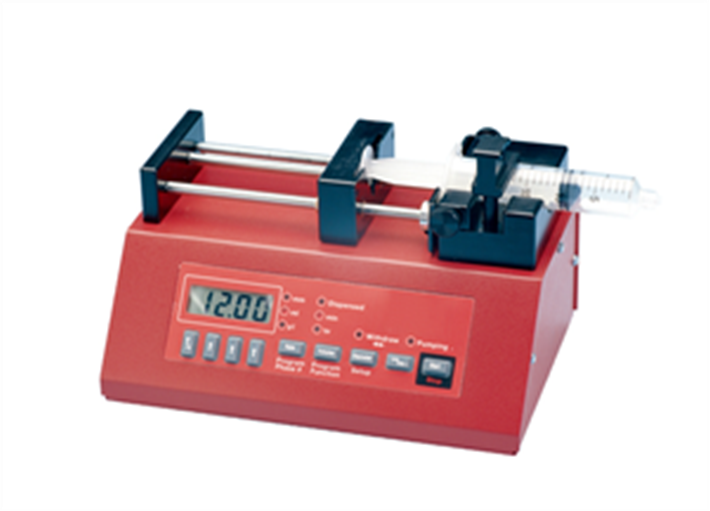
Another possible cleaning method involves the use of two syringes of appropriate volume connected to the liquid ports of the sample cell. In the appropriate order (numerical), introduce each cleaning solution into the sample cell and flush it back and forth between the syringes 10-12 times. Repeat this procedure until there is no noticeable improvement in sample cell performance.
Final Rinsing Procedure
Once the technician identifies the point where subsequent cleaning cycles no longer improve the performance of the flowcell, flush the unit with ultrapure water for a period of at least 15 minutes to ensure that all cleaning solutions have been completely removed and there are no persistent residues that might affect flowcell performance or stability.
Example LWCC Measurement Setup with Order code
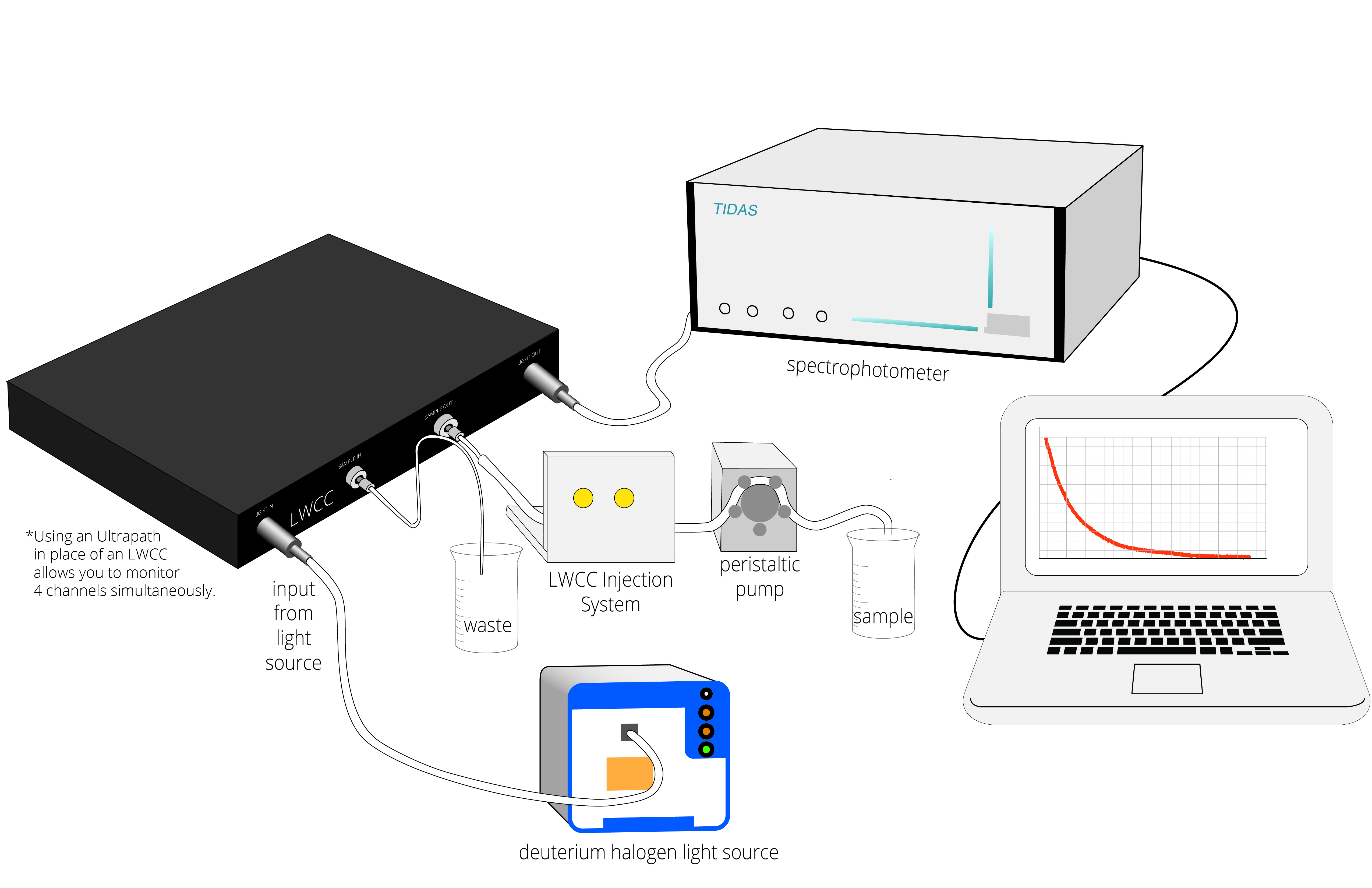
TIDAS E Photo Diode Array Spectrometer UV/VIS (504718)
Deuterium/Halogen Fiber Light Source (D4H)
Liquid Waveguide Capillary Cell, 50 cm pathlength (LWCC-3100)
LWCC Start-up Kit (KITLWCC), which includes two fiber cables (505195), sample injector attachment (58006), MiniStar Peristaltic Pump (MINISTAR) and Waveguide Cleaning Kit.


1.png)


Request
Catalogue
Chat
Print