- Page 1
- Page 2
- Page 3
- Page 4
- Page 5
- Page 6
- Page 7
- Page 8
- Page 9
- Page 10
- Page 11
- Page 12
- Page 13
- Page 14
- Page 15
- Page 16
- Page 17
- Page 18
- Page 19
- Page 20
- Page 21
- Page 22
- Page 23
- Page 24
- Page 25
- Page 26
- Page 27
- Page 28
- Page 29
- Page 30
- Page 31
- Page 32
- Page 33
- Page 34
- Page 35
- Page 36
- Page 37
- Page 38
- Page 39
- Page 40
- Page 41
- Page 42
- Page 43
- Page 44
- Page 45
- Page 46
- Page 47
- Page 48
- Page 49
- Page 50
- Page 51
- Page 52
- Page 53
- Page 54
- Page 55
- Page 56
- Page 57
- Page 58
- Page 59
- Page 60
- Page 61
- Page 62
- Page 63
- Page 64
- Page 65
- Page 66
- Page 67
- Page 68
- Page 69
- Page 70
- Page 71
- Page 72
- Page 73
- Page 74
- Page 75
- Page 76
- Page 77
- Page 78
- Page 79
- Page 80
- Page 81
- Page 82
- Page 83
- Page 84
- Page 85
- Page 86
- Page 87
- Page 88
- Page 89
- Page 90
- Page 91
- Page 92
- Page 93
- Page 94
- Page 95
- Page 96
- Page 97
- Page 98
- Page 99
- Page 100
- Page 101
- Page 102
- Page 103
- Page 104
- Page 105
- Page 106
- Page 107
- Page 108
- Page 109
- Page 110
- Page 111
- Page 112
- Page 113
- Page 114
- Page 115
- Page 116
- Page 117
- Page 118
- Page 119
- Page 120
- Page 121
- Page 122
- Page 123
- Page 124
- Page 125
- Page 126
- Page 127
- Page 128
- Page 129
- Page 130
- Page 131
- Page 132
- Page 133
- Page 134
- Page 135
- Page 136
- Page 137
- Page 138
- Page 139
- Page 140
- Page 141
- Page 142
- Page 143
- Page 144
- Page 145
- Page 146
- Page 147
- Page 148
- Page 149
- Page 150
- Page 151
- Page 152
- Page 153
- Page 154
- Page 155
- Page 156
- Page 157
- Page 158
- Page 159
- Page 160
- Page 161
- Page 162
- Page 163
- Page 164
- Page 165
- Page 166
- Page 167
- Page 168
- Page 169
- Page 170
- Page 171
- Page 172
- Page 173
- Page 174
- Page 175
- Page 176
- Page 177
- Page 178
- Page 179
- Page 180
- Page 181
- Page 182
- Page 183
- Page 184
- Page 185
- Page 186
- Page 187
- Page 188
- Page 189
- Page 190
- Page 191
- Page 192
- Page 193
- Page 194
- Page 195
- Page 196
- Page 197
- Page 198
- Page 199
- Page 200
- Page 201
- Page 202
- Page 203
- Page 204
- Page 205
- Page 206
- Page 207
- Page 208
- Page 209
- Page 210
- Page 211
- Page 212
- Flash version
© UniFlip.com
Accessories
Z-Dimensions Are Not Created Equal
Cuvettes come in a variety of shapes and sizes, but one of the most important specifications of a cuvette is its Z-dimension. The Z-dimension of an instrument (cuvette holder or spectrometer) is the distance from the bottom of the cuvette chamber floor to the center of its light beam (see image). A cuvette’s Z-dimension must match the Z-dimension of the instrument with which it will be used.
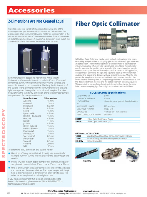
Fiber Optic Collimator
SPEC TROS CO PY
Each manufacturer designs its instruments with a specific Z-dimension. Common Z-dimensions include 8.5 and 15mm, and sometimes 20mm. When purchasing small volume cuvettes, the correct Z-dimension becomes critical. Matching the Z-dimension of the cuvette to the Z-dimension of the instrument ensures that the light beam passes through the center of small samples. The table below shows the standard Z-dimension of the spectrometer sample compartments for many manufacturers. Manufacturer Z-Dimension Agilent® 15 mm Avantes® 15 mm Beckman® 8.5 mm Bio-Rad® 8.5 mm Cecil® 15 mm Eppendorf® 8.5 mm Hewlett – Packard® 15 mm Hitachi® 8.5 mm Jasco® 11 mm J & M® 8.5 mm Ocean Optics® 15 mm Perkin – Elmer® 15 mm Pharmacia® 15 mm Shimadzu® 15 mm Spectronics® 8.5 mm Stellarnet® 15 mm Turner® 8.5 mm Varian ® 20 mm WPI 15mm To determine the Z-dimension of a cuvette holder: ● Use strips of heavy paper that will fit neatly into a cuvette (for example, 12mm x 50mm) and not allow light to pass through the cuvette. ● Poke a tiny hole in each paper “sample.” For example, one paper sample could have a hole at 8.5mm, one at 15mm, one at 20mm. ● One at a time, insert the paper samples into the cuvette and place the cuvette into the cuvette holder. The paper sample with the pin hole at the instrument’s Z-dimension will allow light to pass. The other paper samples will not allow light to pass. If you have an instrument that is not on the list and need to know its Z-dimension, please contact WPI at 941-371-1003 or technicalsupport@wpiinc.com.
WPI’s Fiber Optic Collimator can be used for both collimating a light beam emitted by an optical fiber or coupling light from a collimated light beam into an optical fiber. The numerical aperture of the collimator is optimized for maximum coupling efficiency into typical fused silica fibers. The collimator can, for example, be used to guide a parallel light beam through a sample cuvette or an optical filter with virtually no optical losses. In this application, one collimator collimates the light into a parallel beam 5 mm in diameter, enabling it to pass a long distance without losing the energy. After the light passes the sample media, a second collimator can be used to collect the beam into the receiving fiber. A unique design feature of this collimator is that the distance between the lens and the optical fiber can be easily adjusted. This permits it to be used as a focusing device or for fine-tuning the color balance when coupling light from a light source into multimode fibers.
COLLIMATOR Specifications
LENS DIAMETER LENS FOCAL DISTANCE LENS MATERIAL 1) WAVELENGTH RANGE MOUNTING THREADS DIVERGENCE FIBER CONNECTOR INTERFACE 5 mm 10 mm Ultraviolet grade synthetic fused silica (KU220 nm-2 µm 3/8-24 UNF < 0.1 rad for 1 mm core fiber SMA or ST
300051 300052
Fiber Optic Collimator (SMA) Fiber Optic Collimator (ST)
OPTIONAL ACCESSORIES 13395 SMA Bulkhead Feedthru connector/coupler, D-hole 13370 SMA half-length Bulkhead coupler/connector CC-3-UV Cosine Corrector
CC-3-UV
13395
13370
198
UK: Tel: +44 (0)1462 424700 • wpiuk@wpi-europe.com
World Precision Instruments
www.wpiinc.com Germany: Tel: +49 (0)30-6188845 • wpide@wpi-europe.com US: Tel: 941-371-1003 • sales@wpiinc.com