- Page 1
- Page 2
- Page 3
- Page 4
- Page 5
- Page 6
- Page 7
- Page 8
- Page 9
- Page 10
- Page 11
- Page 12
- Page 13
- Page 14
- Page 15
- Page 16
- Page 17
- Page 18
- Page 19
- Page 20
- Page 21
- Page 22
- Page 23
- Page 24
- Page 25
- Page 26
- Page 27
- Page 28
- Page 29
- Page 30
- Page 31
- Page 32
- Page 33
- Page 34
- Page 35
- Page 36
- Page 37
- Page 38
- Page 39
- Page 40
- Page 41
- Page 42
- Page 43
- Page 44
- Page 45
- Page 46
- Page 47
- Page 48
- Page 49
- Page 50
- Page 51
- Page 52
- Page 53
- Page 54
- Page 55
- Page 56
- Page 57
- Page 58
- Page 59
- Page 60
- Page 61
- Page 62
- Page 63
- Page 64
- Page 65
- Page 66
- Page 67
- Page 68
- Page 69
- Page 70
- Page 71
- Page 72
- Page 73
- Page 74
- Page 75
- Page 76
- Page 77
- Page 78
- Page 79
- Page 80
- Page 81
- Page 82
- Page 83
- Page 84
- Page 85
- Page 86
- Page 87
- Page 88
- Page 89
- Page 90
- Page 91
- Page 92
- Page 93
- Page 94
- Page 95
- Page 96
- Page 97
- Page 98
- Page 99
- Page 100
- Page 101
- Page 102
- Page 103
- Page 104
- Page 105
- Page 106
- Page 107
- Page 108
- Page 109
- Page 110
- Page 111
- Page 112
- Page 113
- Page 114
- Page 115
- Page 116
- Page 117
- Page 118
- Page 119
- Page 120
- Page 121
- Page 122
- Page 123
- Page 124
- Page 125
- Page 126
- Page 127
- Page 128
- Page 129
- Page 130
- Page 131
- Page 132
- Page 133
- Page 134
- Page 135
- Page 136
- Page 137
- Page 138
- Page 139
- Page 140
- Page 141
- Page 142
- Page 143
- Page 144
- Page 145
- Page 146
- Page 147
- Page 148
- Page 149
- Page 150
- Page 151
- Page 152
- Page 153
- Page 154
- Page 155
- Page 156
- Page 157
- Page 158
- Page 159
- Page 160
- Page 161
- Page 162
- Page 163
- Page 164
- Page 165
- Page 166
- Page 167
- Page 168
- Page 169
- Page 170
- Page 171
- Page 172
- Page 173
- Page 174
- Page 175
- Page 176
- Page 177
- Page 178
- Page 179
- Page 180
- Page 181
- Page 182
- Page 183
- Page 184
- Page 185
- Page 186
- Page 187
- Page 188
- Page 189
- Page 190
- Page 191
- Page 192
- Page 193
- Page 194
- Page 195
- Page 196
- Page 197
- Page 198
- Page 199
- Page 200
- Page 201
- Page 202
- Page 203
- Page 204
- Page 205
- Page 206
- Page 207
- Page 208
- Page 209
- Page 210
- Page 211
- Page 212
- Flash version
© UniFlip.com
A395 Linear Stimulus Isolator
Replicates a programmed waveform of any shape or polarity
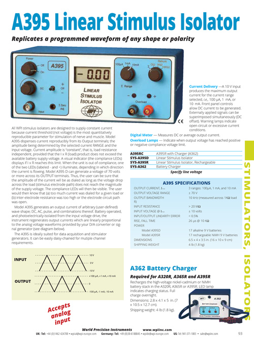
Current Delivery —A 10 V input produces the maximum output current for the current range selected, i.e., 100 µA, 1 mA, or 10 mA. Front panel controls allow DC current to be generated. Externally applied signals can be superimposed simultaneously (DC offset). Warning lamps indicate open circuit or excessive current conditions. Digital Meter — Measures DC or average output current. Overload Lamps — Indicate when output voltage has reached positive or negative compliance voltage limit. A395RC SYS-A395D SYS-A395R SYS-A362 A395R with Charger (A362) Linear Stimulus Isolator Linear Stimulus Isolator, Rechargeable Battery Charger Specify line voltage
All WPI stimulus isolators are designed to supply constant current because current threshold (not voltage) is the most quantitatively reproducible parameter for stimulation of nerve and muscle. Model A395 dispenses current reproducibly from its Output terminals; the amplitude being determined by the selected current RANGE and the input voltage. Current amplitude is “constant”, that is, load resistance independent, provided that the I x R (load) product does not exceed the available battery supply voltage. A visual indicator (the compliance LEDs) displays if I x R reaches this limit. When the unit is out of compliance, one of the two LEDs (labeled - and +) illuminate, depending in which direction the current is flowing. Model A395 D can generate a voltage of 70 volts or more across its OUTPUT terminals. Thus, the user can be sure that the amplitude of the current will be as dialed as long as the voltage drop across the load (stimulus electrode path) does not reach the magnitude of the supply voltage. The compliance LEDs will then be visible. The user would then know that (a) too much current was dialed for a given load or (b) inter-electrode resistance was too high or the electrode circuit path was open. Model A395 generates an output current of arbitrary (user-defined) wave shape; DC, AC, pulse, and combinations thereof. Battery operated, and photoelectrically-isolated from the input voltage drive, the instrument regenerates output currents which are linearly proportional to the analog voltage waveforms provided by your D/A converter or signal generator (see diagram below). The A395 is ideally suited for data acquisition and stimulator generators. It can be easily daisy-chained for mutiple channel requirements.
STIMULATORS, ISOLATORS
OUTPUT CURRENT, Imax OUTPUT BANDWIDTH R) INPUT RESISTANCE INPUT VOLTAGE @ Imax
A395 SPECIFICATIONS
3 ranges: 100µA, 1 mA, and 10 mA ± 70 V 10 kHz (measured across 1KΩ load > 20 MΩ ± 10 volts < 0.5% 26 µs @ 10 KΩ 17 alkaline 9 V batteries 17 rechargeable NiMH 9 V batteries 6.5 x 4 x 3.5 in. (16 x 10 x 9 cm) 4 lb (1.8 kg)
OUTPUT VOLTAGE RANGE
INPUT/OUTPUT LINEARITY ERROR RISE, FALL TIME POWER Model A395D Model A395R DIMENSIONS SHIPPING WEIGHT
INPUT
10 V 0V -10 V +100 µA, +1 mA, +10 mA
A362 Battery Charger
Required for A320R, A365R and A395R
Recharges the high-voltage nickel-cadmium or NiMH battery stack in the A320R, A365R or A395R. LED lamp indicates charging status. Full charge overnight. Dimensions: 2.8 x 4.1 x 5 in. (7 x 10.5 x 12.7 cm). Shipping weight: 4 lb (1.8 kg).
OUTPUT
0 -100 µA, -1 mA, -10 mA
pts Acce og anal t inpu
UK: Tel: +44 (0)1462 424700 • wpiuk@wpi-europe.com
World Precision Instruments
www.wpiinc.com Germany: Tel: +49 (0)30-6188845 • wpide@wpi-europe.com US: Tel: 941-371-1003 • sales@wpiinc.com
93